RadioLab - RF Experimentation Board
Modular RF experimentation platform
Learn, build and experiment with RF circuits.
As featured in

What is it?
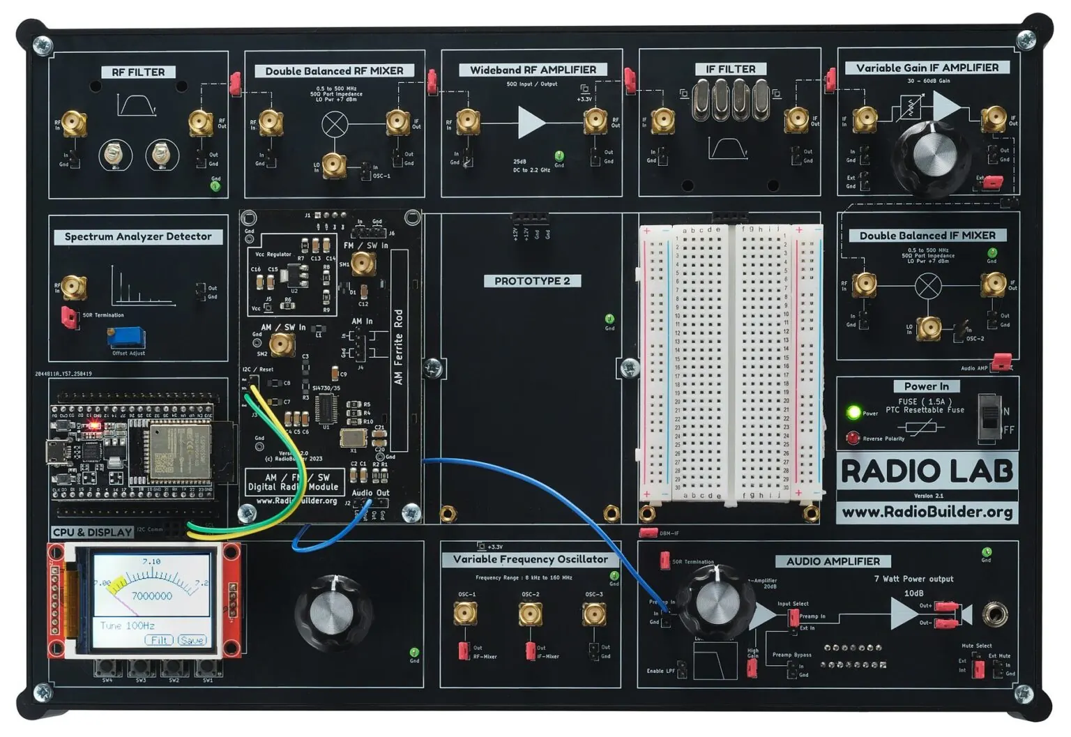
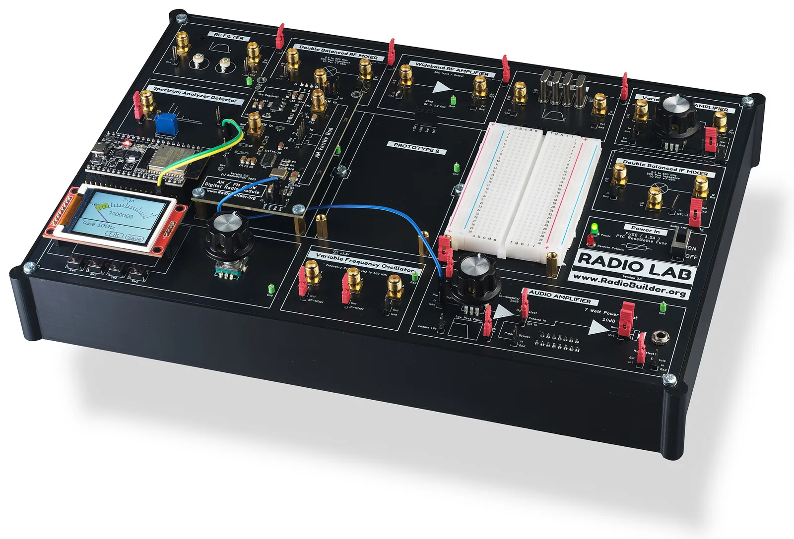
The RadioLab is a modular RF experimentation platform built from proven RF and control blocks - reconfigure them for fast experimentation, hands-on RF learning, or testing your own designs.
Expand it
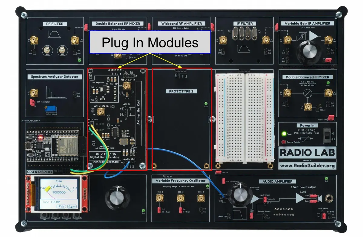
Five plug-in modules (Software Defined Radio, a universal digital LW/MW/SW/FM radio, discrete transistor audio amplifier, CW Transceiver and analog FM receiver) extend the RadioLab system without touching the existing build.
Open by design
The platform is open: schematics and firmware are free to download - nothing is a black box, and nothing needs a proprietary toolchain to modify.
Open by design
Complete schematics, free to download.
Every sheet - all 13, RF blocks through power supply - free to download. No black boxes.
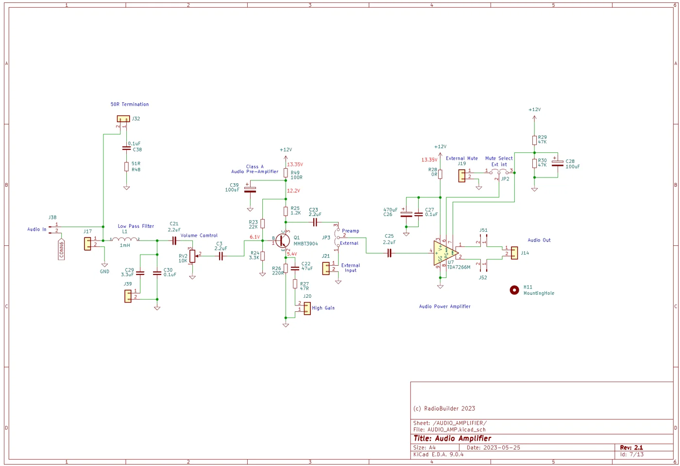
- Learn the actual circuitEvery stage has design values - not a simplified block diagram.
- Cross-reference with the boardMatch each schematic sheet straight to the physical module in front of you.
- Reuse proven circuitsUse these proven circuits in your own designs.
- Repair anythingIf you ever need to repair, you can trace a fault to the exact component, instead of guessing at a black box.
Open source
Firmware you can read, fork, and modify
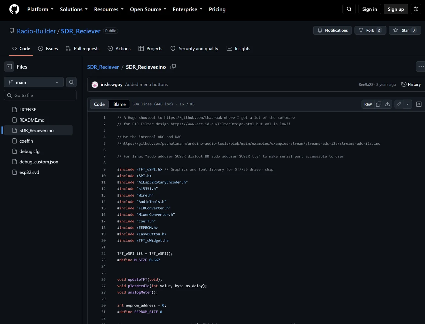
Every build runs on commented open source Arduino C/C++ - no compiled blob, no locked bootloader, no license to unlock.
- Full source, not a binaryEvery project comes with readable .ino/.h files - flash it, read it, and know exactly what's running on the ESP32.
- Start with working codeIf you are inexperienced you can use the code as is and it just works.
- Modify itChange the code to your preferences if you are learning or experienced with code.
- Built on standard librariesTFT_eSPI for the display, si5351 for the clock generator, AudioTools for the DSP chain - documented libraries, not custom black-box drivers.
Expand it
Plug-in modules expand what the RadioLab can do
Use plug-in modules to make software-defined radios, analog FM broadcast, universal digital radio, class AB audio amplifier and CW transceiver.
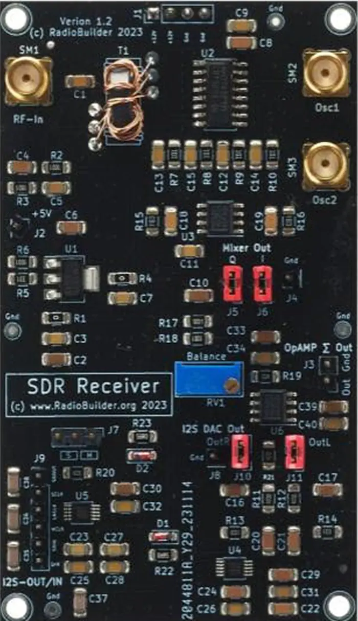
Software Defined Radio
Discover I/Q signals, and experiment with DSP filtering for USB/LSB and CW demodulation.
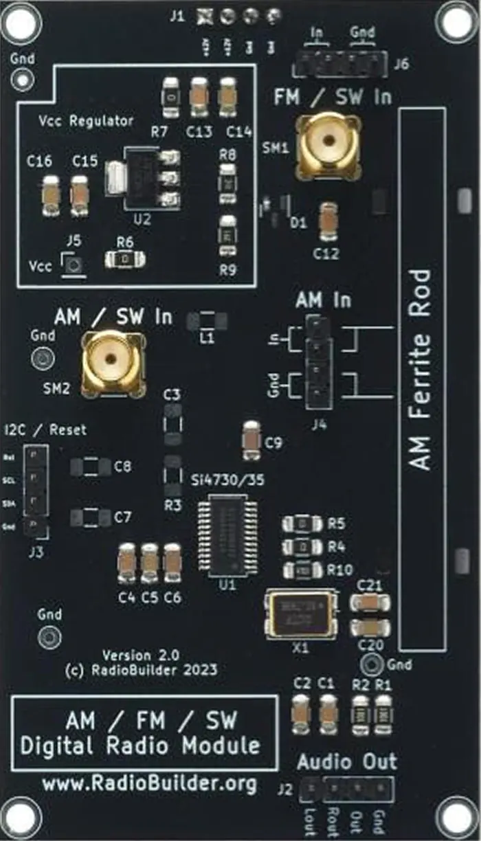
Universal Digital Radio
LW, MW, SW and FM reception in one module. Decode broadcast, SSB and CW with audio bandwidth filter selection.
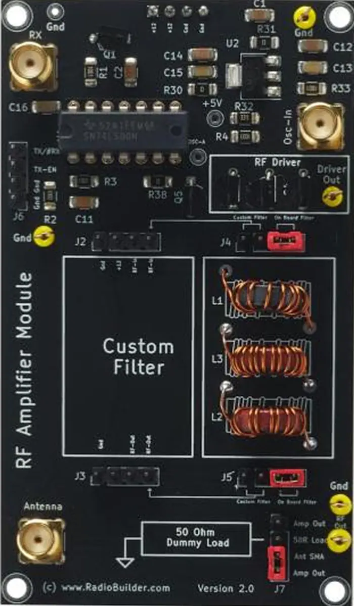
CW Transceiver
Generate a CW signal and build transceivers. Safely terminate it into a dummy load for testing.
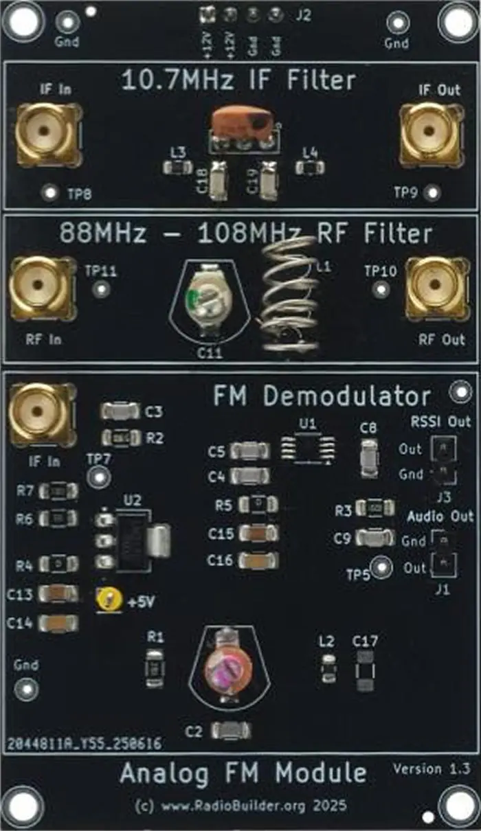
Analog FM Receiver
A classic analog FM broadcast receiver stage with RF filter, IF filter and FM limiter/demodulator.
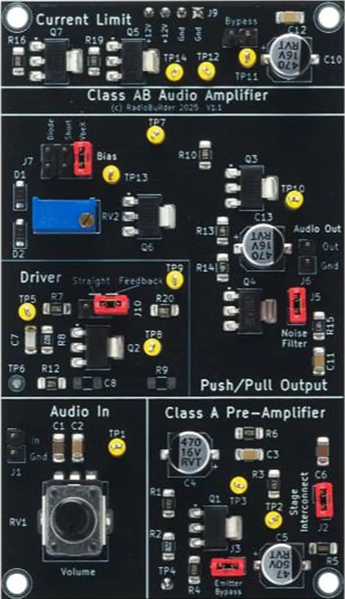
Discrete Transistor Audio Amplifier
Experiment with a Class A preamplifier, Vbe or diode bias, a push/pull output stage, current limiting for safety, and compare feedback for amplifier quality.
Process
How the RadioLab works
Build the RadioLab system
SMT components arrive pre-soldered. You assemble the through-hole components and wire up the power section.
Patch it together
Jumpers and SMA cables connect each block, so you reconfigure the system quickly and easily.
Experiment, section by section
Test one block at a time - a filter, a mixer, an oscillator - and build up to a full receiver or a circuit of your own.
Expand, or design your own
Add a plug-in module, or use the prototyping area to swap your own circuit in and out while using the proven building blocks.
Pricing
Get the RadioLab
Worldwide tracked shipping.
Complete Kit
- Main PCB - all SMT components pre-soldered
- 40M RF bandpass filter
- SSB IF filter
- ESP32 controller
- Colour TFT display
- RF connectors
- Enclosure
Complete Kit + Plug-in Modules
- Everything in the Complete Kit
- Discrete transistor audio amplifier
- CW Transceiver
- Analog FM receiver
- Software defined radio (SDR)
- Universal digital radio - LW/MW/SW/FM
Plug-in Modules
For builders who already own a Complete Kit.
- Discrete transistor audio amplifier
- CW Transceiver
- Analog FM receiver
- Software defined radio (SDR)
- Universal digital radio - LW/MW/SW/FM
Trusted by the amateur radio community
What builders say
This is a fantastic kit. I purchased one as a Christmas gift for a friend's son, and he is now deeply engaged in learning the fundamentals of communications electronics and coding at the same time. It has already sparked an interest in electronics engineering as a potential college path. A great kit for keeping curious young people motivated and learning.
Hugh MaguireA very well designed kit that is simple and easy to build. It is extremely useful for training future radio amateurs. Communication with Louis, the designer, was excellent. A friendly and supportive OM. Thank you.
Jean Pierre, F6IHCThe RadioBuilder RadioLab is a powerful and flexible platform for designing, building, and testing advanced radio projects. The section by section approach makes it ideal for both learning and experimentation.
Glen Popiel, ARRL KW5GPWhat I really like about the RadioLab is that simply through the use of jumpers and SMA cables, you can experiment on just one section of the radio at a time, tremendously speeding up the design and testing process.
QST Magazine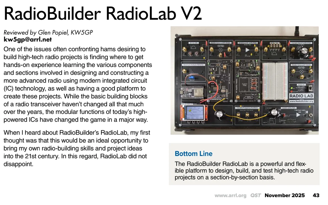
Read the full QST review
RadioBuilder RadioLab V2, reviewed by Glen Popiel, KW5GP - QST Magazine, November 2025.

Winner, IRTS Folen Shield 2024
For ham radio constructed equipment.
Before you buy
Frequently asked questions
A soldering iron and a 12V power supply to build it. Once you start experimenting, a multimeter and an oscilloscope will be useful.
Shipped worldwide from Ireland. Shipping cost is calculated by weight, size and destination at checkout, and you're responsible for any customs duties or import taxes charged in your country.
Kits are sold assembly-required, so once soldering has started we can't take it back - the finished result depends on your own build quality, which we can't guarantee after the fact. If you receive the wrong item, contact us within 7 days and we'll sort a return.
Documentation, wiring diagrams and firmware live on GitHub. For build support, join the RadioBuilder group on groups.io - or use the contact form below.
Under the hood
The building blocks
Twelve RF and control modules make up the RadioLab system. Patch them together with jumpers and SMA cables to build your own RF circuits - from a single filter stage up to a full receiver.
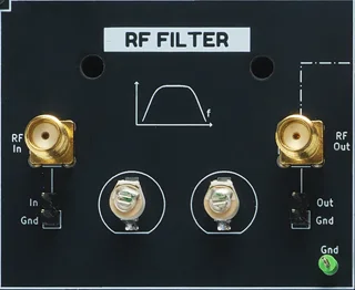
RF Filter
Fixed bandpass filter stage - the first block in the RF chain, rejecting out-of-band signals before they reach the mixer.
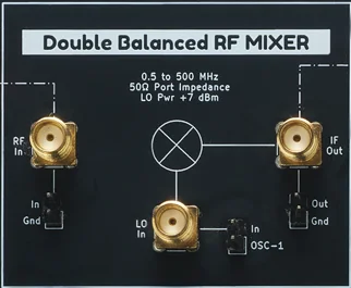
RF Mixer
Double-balanced, 0.5–500MHz, 50Ω ports, +7dBm LO drive. Converts the incoming RF to whatever IF your build needs.
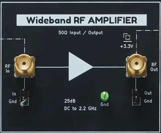
RF Amplifier
Wideband, 25dB gain, DC to 2.2GHz. Boosts weak signals before mixing, or drives a stage that needs more level.
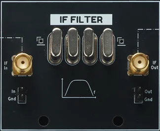
IF Filter
Switchable bandpass filter at IF, selected via onboard DIP switches. Sets the receiver's selectivity and image rejection.
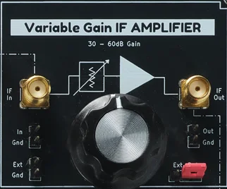
IF Amplifier
Variable gain, 30–60dB, adjustable via onboard pot or external control. The main gain block between IF filter and demodulator.
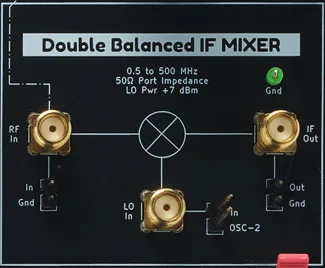
IF Mixer
Double-balanced, 0.5–500MHz, 50Ω ports, driven from OSC-2. Second conversion stage for superhet builds.
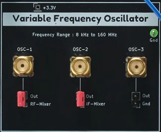
Variable Frequency Oscillator
Three outputs, 8kHz–160MHz, feeding the RF mixer, IF mixer, or an external load independently. The tunable heart of every receiver build.
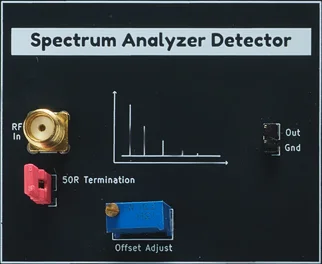
Spectrum Analyzer Detector
RF detector front end with 50Ω termination and offset trim, turning the ESP32 and TFT display into a swept spectrum analyzer.
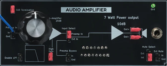
Audio Amplifier
20dB preamp feeding a 10dB, 7W output stage, with switchable input, bypass, high-gain, and mute. Drives a speaker or headphones straight off the board.
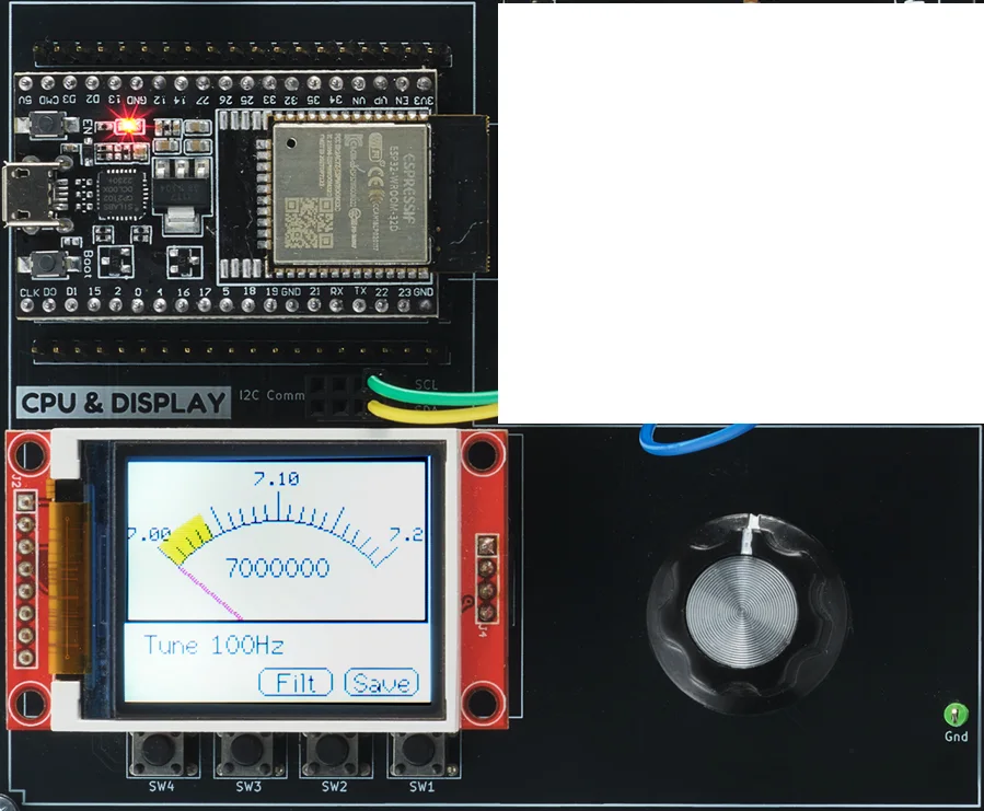
CPU & Display
ESP32 controller driving a colour TFT with tuning readout and four front-panel buttons. Runs every build's UI and the frequency counter.
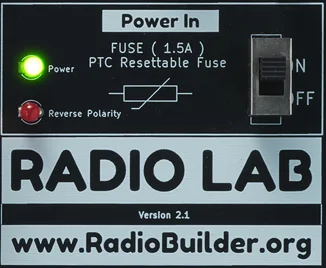
Power In
1.5A PTC resettable fuse, reverse-polarity protection, and power/fault LEDs. One switch, no blown fuses to replace.
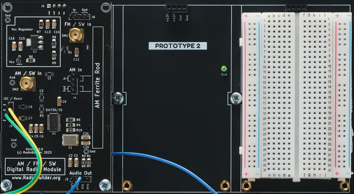
Prototype Area
Full-size breadboard with a dedicated +12V/GND header, wired straight into the signal path. Room to add your own circuit without disturbing the rest of the board.
Get in touch
Contact
Questions before you buy, or need a hand with a build? Send a message - you'll hear back from the person who designed the board.
Support
Build support
Join the RadioBuilder group on groups.io for build help from other builders.
Visit groups.io →Shipping
Ships worldwide from Ireland. See the FAQ above for return and customs details.